Delica Central Locking Wiring Diagram

Wiring Diagram Toyota Hiace Wiring Diagram 1998 Toyota Hiace

Delica Club View Topic Remote Central Locking Hook Up L400
Delica Club View Topic Central Locking Through The Key

Lug Nut Size Chart Van Club Wheel Size Bolt Pattern Lug

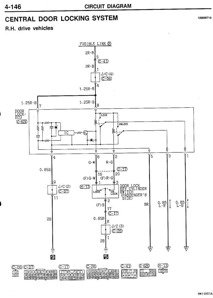
Dw 4644 Central Door Locking Wiring And Circuit Diagram Circuit

12da90 Pajero Central Locking Wiring Diagram Wiring Resources
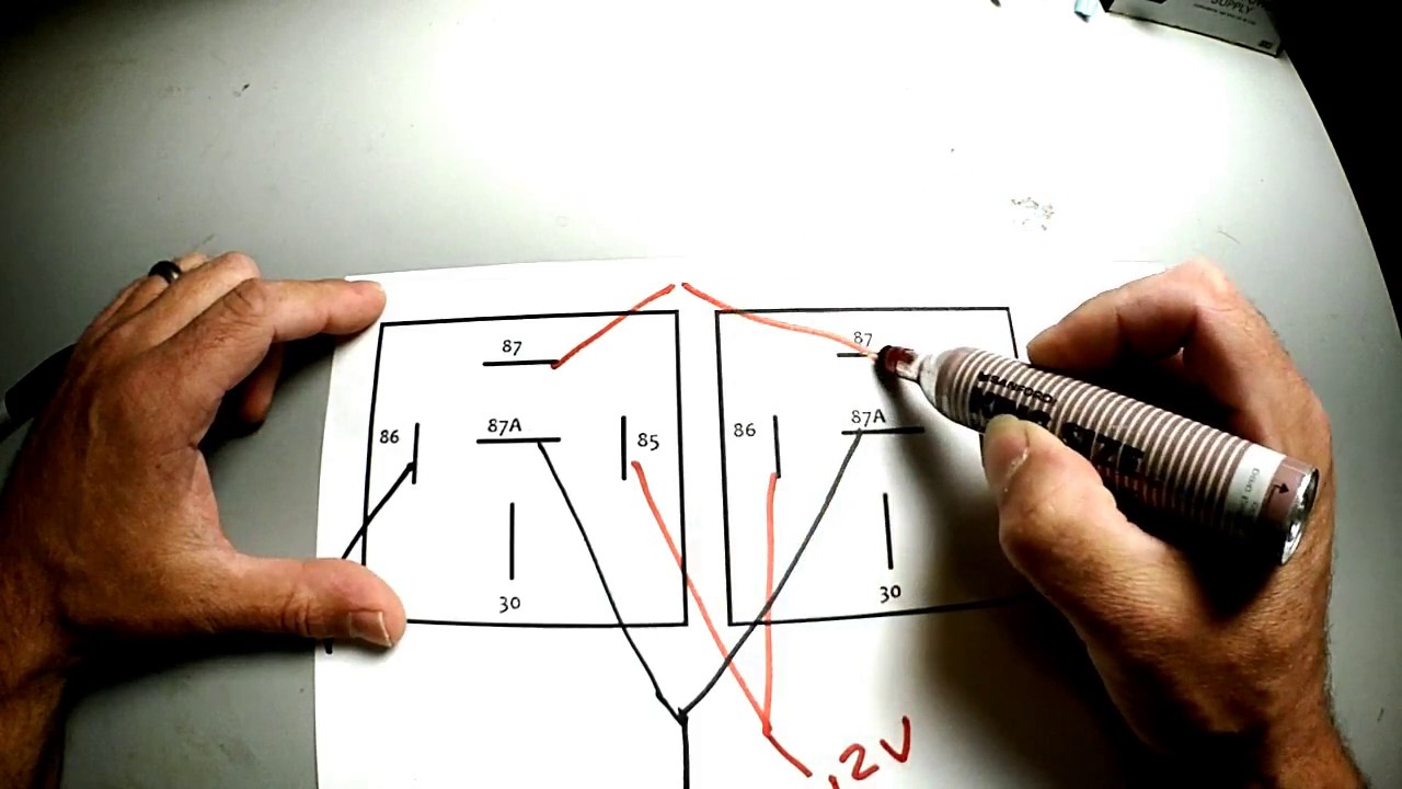
Connect between the wires you think are the operating wires and chassis if the bulb lights wrong wire the car locks unlocks wire identified.
Delica central locking wiring diagram. Bose wiring diagrams posted on sep 10 2018 by jennifer s. Here is the wiring diagram for the central locking kit ive got. Offers rich clear audio performance in a compact design for your iphone or ipod with a. But now the other three doors are locking unlocking when i touch the live feed wire to the 12v wire and the drivers door lock isnt.
I was hoping that the other two wires the two small wires connected to the driver s actuator were sense wires to control the lock control unit. So far i have connected the top orange wire to the drivers door lock my theory being that i only need to actuate the drivers door. Subscribe subscribed unsubscribe 169k. Green you can also find other images like wiring diagram parts diagram replacement parts electrical diagram repair manuals engine diagram.
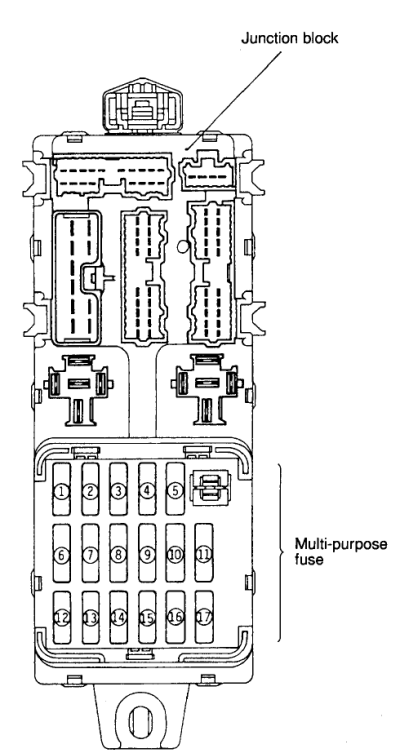
The switch when moved in either direction applies both power and ground directly to motor legs without the use of any relays. Power door locks have been around for many year but manufacturers use different wiring schemes. No other wiring related to the central locking has been modified touched. Compartment fuse box mitsubishi delica l400 fuse box diagram compartment fuse box.
Power door locks wiring diagram adptraining. One wiring scheme is resistive rest at ground which has been used in the past by various. Except at the switch in this case both motor legs rest at ground. This is a diagram of the unit the seller was able to provide.
Door locks 5 wire alternating 12 volts positive type c relay wiring diagram. Sharing delica information and experiences. Mitsubishi delica l400 fuse box diagram. Can someone give me a total idiot guide to wiring it in.
And the useless instructions with the new unit dont share much on the central locking part of the wiring only the alarm part which is easy to work out. Most central locking works by connecting the wires to ground to operate you can check this using a test bulb any 12 volt bulb say 5 or 10 watts.
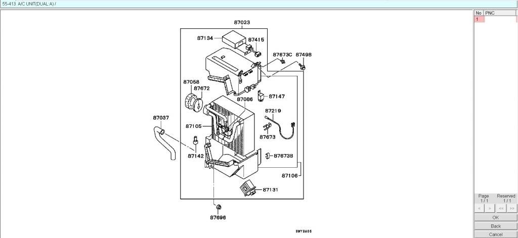
Delica Club View Topic Ac Control Unit For L400
The Door Lock System And Affiliated Electric Circuit Of The

Mitsubishi Delica L300 Starwagon Electrical Issue Fix No

Fuse Box Location And Diagrams Mitsubishi Delica L400 Space
Mitsubishi Delica Owners Club Uk View Topic How To Central
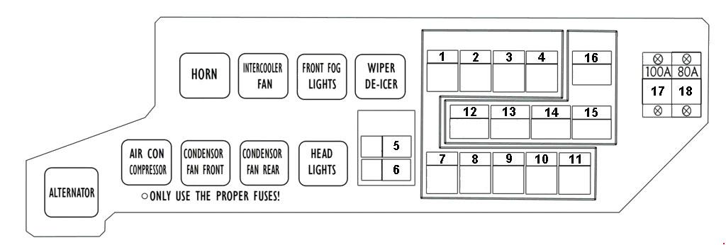
Mitsubishi Delica L400 Fuse Box Diagram Auto Genius

Oddie Bradbury And Cull Folder Design Commercial Design Design

New Custom Center Console Lockbox For Delica L400 With Images

Mitsubishi L300 Delica How Not To Fix Instruments Illumination

Beaded Earring Pattern Brick Stitch Pdf Download 092e 2 Variants

Mitsubishi Delica User Manual Spacegear 1997 E12

Lovely Flower Heart Delica Seed Beaded Dangle Earrings On Etsy

B56 Mitsubishi Delica Wiring Diagram Wiring Resources